|
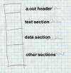
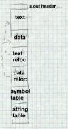
Figure 1: Simplifed a.out
a.out header text section data section other sections |
| Compilers and assemblers create object files containing the generated binary code and data for a source file. Linkers combine multiple object files into one, loaders take object files and load them into memory. (In an integrated programming environment, the compilers, assemblers, and linkers are run implicitly when the user tells it to build a program, but they're there under the covers.) In this chapter we delve into the details of object file formats and contents. |
Not all object formats contain all of these kinds of information, and it's possible to have quite useful formats with little or no information beyond the object code.
A linkable file contains extensive symbol and relocation information needed by the linker along with the object code. The object code is often divided up into many small logical segments that will be treated differently by the linker. An executable file contains object code, usually page aligned to permit the file to be mapped into the address space, but doesn't need any symbols (unless it will do runtime dynamic linking), and needs little or no relocation information. The object code is a single large segment or a small set of segments that reflect the hardware execution environment, most often read-only vs. read-write pages. Depending on the details of a system's runtime environment, a loadable file may consist solely of object code, or may contain complete symbol and relocation information to permit runtime symbolic linking.
There is some conflict among these applications. The logically oriented grouping of linkable segments rarely matches the hardware oriented grouping of executable segments. Particularly on smaller computers, linkable files are read and written by the linker a piece at a time, while executable files are loaded in their entirely into main memory. This distinction is most obvious in the completely different MS-DOS linkable OMF format and executable EXE format.
We'll tour a series of popular formats, starting with the simplest, and working up to the most complicated.
The segmented architecture of the x86 makes this work. Since all x86 program addresses are interpreted relative to the base of the current segment and the segment registers all point to base of the segment, the program is always loaded at segment-relative location 0x100. Hence, for a program that fits in a single segment, no fixups are needed since segment-relative addresses can be determined at link time.
For programs that don't fit in a single segment, the fixups are the programmer's problem, and there are indeed programs that start out by fetching one of their segment registers, and adding its contents to stored segment values elsewhere in the program. Of course, this is exactly the sort of tedium that linkers and loaders are intended to automate, and MS-DOS does that with .EXE files, described later in this chapter.
In the simplest case, an a.out file consisted of a small header followed by the executable code (called the text section for historical reasons) and the initial values for static data, Figure 1. The PDP-11 had only 16 bit addressing, which limited programs to a total of 64K. This limit quickly became too small, so later models in the PDP-11 line provided separate address spaces for code (I for Instruction space) and data (D space), so a single program could contain both 64K of code and 64K of data. To support this feature, the compilers, assembler, and linker were modified to create two-section object files, with the code in the first section and the data in the second section, and the program loader loaded the first section into a process' I space and the second into the D space.
|
|
Figure 1: Simplifed a.out
a.out header text section data section other sections |
Separate I and D space had another performance advantage: since a program couldn't change its own I space, multiple copies of a single program could share a single copy of a program's code, while keeping separate copies of the program's data. On a time-shared system like Unix, multiple copies of the shell (the command interpreter) and network daemons are common, and shared program code saves considerable real memory.
The only currently common computer that still uses separate addressing for code and data is the 286 (or 386 in 16 bit protected mode). Even on more modern machines with large address spaces, the operating system can handle shared read-only code pages in virtual memory much more efficiently than read/write pages, so all modern loaders support them. This means that linker formats must at the least mark read-only versus read-write sections. In practice, most linker formats have many sections, such as read-only data, symbols and relocation for subsequent linking, debugging symbols, and shared library information. (Unix convention confusingly calls the file sections segments, so we use that term in discussions of Unix file formats.)
|
Figure 2: a.out header
|
The magic number a_magic indicates what kind of executable file this is. ( Make this a footnote: Historically, the magic number on the original PDP-11 was octal 407, which was a branch instruction that would jump over the next seven words of the header to the beginning of the text segment. That permitted a primitive form of position independent code. A bootstrap loader could load the entire executable including the file header to be loaded by into memory, usually at location zero, and then jump to the beginning of the loaded file to start the program. Only a few standalone programs ever used this ability, but the 407 magic number is still with us 25 years later.) Different magic numbers tell the operating system program loader to load the file in to memory differently; we discuss these variations below. The text and data segment sizes a_text and a_data are the sizes in bytes of the read-only code and read-write data that follow the header. Since Unix automatically initializes newly allocated memory to zero, any data with an initial contents of zero or whose contents don't matter need not be present in the a.out file. The uninitialized size a_bss says how much uninitialized data (really zero-initialized) data logically follows the data in the a.out file.
The a_entry field gives the starting address of the program, while a_syms, a_trsize, and a_drsize say how much symbol table and relocation information follow the data segment in the file. Programs that have been linked and are ready to run need no symbol nor relocation info, so these fields are zero in runnable files unless the linker has included symbols for the debugger.
|
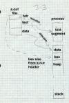
Figure 3: Loading an a.out into a process
picture of file and segments with arrows pointing out data flows |
This scheme (known as NMAGIC, where the N means new, as of about 1975) works quite well, and PDP-11 and early VAX Unix systems used it for years for all object files, and linkable files used it throughout the life of the a.out format into the 1990s. When Unix systems gained virtual memory, several improvements to this simple scheme sped up program loading and saved considerable real memory.
On a paging system, the simple scheme above allocates fresh virtual memory for each text segment and data segment. Since the a.out file is already stored on the disk, the object file itself can be mapped into the process' address space. This saves disk space, since new disk space for virtual memory need only be allocated for pages that the program writes into, and can speed program startup, since the virtual memory system need only load in from disk the pages that the program's actually using, not the whole file.
A few changes to the a.out format make this possible, Figure 4,. and create what's known as ZMAGIC format. These changes align the segments in the object file on page boundaries. On systems with 4K pages, the a.out header is expanded to 4K, and the text segment's size is rounded up to the next 4K boundary. There's no need to round up the size of the data segment, since the BSS segment logically follows the data segment, and is zeroed by the program loader anyway.
|
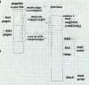
Figure 4: Mapping an a.out into a process
Picture of file and segments, with page frames mapping into segments |
ZMAGIC files reduce unneeded paging, but at the cost of wasting a lot of disk space. The a.out header is only 32 bytes long, yet an entire 4K of disk space is allocated. The gap between the text and data also wastes 2K, half a 4K page, on average. Both of these are fixed in the compact pagable format known as QMAGIC.
Compact pagable files consider the a.out header to be part of the text segment, since there's no particular reason that the code in the text segment has to start at location zero. Indeed, program zero is a particularly bad place to load a program since uninitialized pointer variables often contain zero. The code actually starts immediately after the header, and the whole page is mapped into the second page of the process, leaving the first page unmapped so that pointer references to location zero will fail, Figure 5. This has the harmless side-effect of mapping the header into the process as well.
|
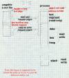
Figure 5: Mapping a compact a.out into a process
Picture of file and segments, with page frames mapping into segments |
The text and data segments in a QMAGIC executable are each rounded up to a full page, so the system can easily map file pages to address space pages. The last page of the data segment is padded out with zeros for BSS data; if there is more BSS data than fits in the padding area, the a.out header contains the size of the remaining BSS area to allocate.
Although BSD Unix loads programs at location zero (or 0x1000 for QMAGIC), other versions of Unix load programs at other addresses. For example, System V for the Motorola 68K series loads at 0x80000000, and for the 386 loads at 0x8048000. It doesn't matter where the load address is so long as it's page aligned, and the linker and operating system can permanently agree what it is.
In these cases, executable files contain relocation entries often called fixups that identify the places in the program where addresses need to be modified when the program is loaded. One of the simplest formats with fixups is the MS-DOS EXE format.
As we saw with the .COM format above, DOS loads a program into a contiguous chunk of available real-mode memory. If the program doesn't fit in one 64K segment, the program has to use explicit segment numbers to address program and data, and at load time the segment numbers in the program have to be fixed up to match the address where the program is actually loaded. The segment numbers in the file are stored as though the program will be loaded at location zero, so the fixup action is to add to every stored segment number the base paragraph number at which the program is actually loaded. That is, if the program is loaded at location 0x5000, which is paragraph 0x500, a reference to segment 12 is relocated to be a reference to segment 512. The offsets within the segments don't change, since the program is relocated as a unit, so the loader needn't adjust anything other than the segment numbers.
Each .EXE File starts with a header shown in Figure 6. Following the header is some extra information of variable length (used for overlay loaders, self-extracting archives, and other application-specific hackery) and a list of the fixup addresses in 32 bit segment:offset format. The fixup addresses are relative to the base of the program, so the fixups themselves have to be relocated to find the addresses in the program to change. After the fixups comes the program code. There may be more information, ignored by the program loader, after the code. (In the example below, far pointers are 32 bits with a 16 bit segment number and 16 bit offset.)
|
Figure 6: Format of .EXE file header
|
Loading an .EXE file is only slightly more complicated than loading a .COM file.
Other than the peculiarities associated with segmented addressing, this is a pretty typical setup for program loading. In a few cases, different pieces of the program are relocated differently. In 286 protected mode, which EXE files do not support, each segment of code or data in the executable file is loaded into a separate segment in the system, but the segment numbers cannot for architectural reasons be consecutive. Each protected mode executable has a table near the beginning listing all of the segments that the program will require. The system makes a table of actual segment numbers corresponding to each segment in the executable. When processing fixups, the system looks up the logical segment number in that table and replaces it with the actual segment number, a process more akin to symbol binding than to relocation.
Some systems permit symbol resolution at load time as well, but we save that topic for Chapter 10.
We look at five formats of increasing complexity: relocatable a.out used on BSD UNIX systems, ELF used on System V, IBM 360 objects, the extended COFF linkable and PE executable formats used on 32 bit Windows, and the OMF linkable format used on pre-COFF Windows systems.
|
Figure 7: Simplifed a.out
a.out header text section data section text relocation data relocation symbol table string table |
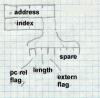
Figure 8 shows the format of a relocation entry. Each entry contains the address within the text or data section to be relocated, along with information that defines what to do. The address is the offset from the beginning of the text or data segment of a relocatable item. The length field says how long the item is, values 0 through three mean 1, 2, 4, or (on some architectures) 8 bytes. The pcrel flag means that this is a ``PC relative'' item, that is, it's used in an instruction as a relative address.
|
Figure 8: Relocation entry format
Draw this with boxes -- four byte address -- three byte index, one bit pcrel flag, 2 bit length field, one bit extern flag, four spare bits |
The extern flag controls the interpretation of the index field to determine which segment or symbol the relocation refers to. If the extern flag is off, this is a plain relocation item, and the index tells which segment (text, data, or BSS) the item is addressing. If the extern flag is on, this is a reference to an external symbol, and the index is the symbol number in the file's symbol table.
This relocation format is adequate for most machine architectures, but some of the more complex ones need extra flag bits to indicate, e.g., three-byte 370 address constants or high and low half constants on the SPARC.
|
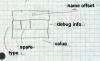
Figure 9: Symbol format
Draw this with boxes, too: - four byte name offset - one byte type - one spare byte - two byte debugger info - four byte value |
Unix compilers permit arbitrarily long identifiers, so the name strings are all in a string table that follows the symbol table. The first item in a symbol table entry is the offset in the string table of the null-terminated name of the symbol. In the type byte, if the low bit is set the symbol is external (a misnomer, it'd better be called global, visible to other modules). Non-external symbols are not needed for linking but can be used by debuggers. The rest of the bits are the symbol type. The most important types include:
As a special case, a compiler can use an undefined symbol to request that the linker reserve a block of storage by that symbol's name. If an undefined external symbol has a non-zero value, that value is a hint to the linker how large a block of storage the program expects the symbol to address. At link time, if there is no definition of the symbol, the linker creates a block of storage by that name in the BSS segment with the size being the largest hint value found in any of the linked modules. If the symbol is defined in any module, the linker uses the definition and ignores the size hints. This ``common block hack'' supports typical (albeit non standard conformant) usage of Fortran common blocks and uninitialized C external data.
ELF files come in three slightly different flavors: relocatable, executable, and shared object. Relocatable files are created by compilers and assemblers but need to be processed by the linker before running. Executable files have all relocation done and all symbols resolved except perhaps shared library symbols to be resolved at runtime. Shared objects are shared libraries, containing both symbol information for the linker and directly runnable code for runtime.
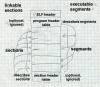
ELF files have an unusual dual nature, Figure 10. Compilers, assemblers, and linkers treat the file as a set of logical sections described by a section header table, while the system loader treats the file as a set of segments described by a program header table. A single segment will usually consist of several sections. For example, a ``loadable read-only'' segment could contain sections for executable code, read-only data, and symbols for the dynamic linker. Relocatable files have section tables, executable files have program header tables, and shared objects have both. The sections are intended for further processing by a linker, while the segments are intended to be mapped into memory.
|
Figure 10: Two views of an ELF file
linking view and execution view, adapted from fig 1-1 in Intel TIS document |
ELF files all start with the ELF header, Figure 11. The header is designed to be decodable even on machines with a different byte order from the file's target architecture. The first four bytes are the magic number identifying an ELF file, followed by three bytes describing the format of the rest of the header. Once a program has read the class and byteorder flags, it knows the byte order and word size of the file and can do the necessary byte swapping and size conversions. Other fields provide the size and location of the section header and program header, if present,
|
Figure 11: ELF header
|
|
Figure 12: Section header
|
Section types include:
A typical relocatable executable has about a dozen sections. Many of the section names are meaningful to the linker, which looks for the section types it knows about for specific processing, while either discarding or passing through unmodified sections (depending on flag bits) that it doesn't know about.
Sections include:
An unusual section type is .interp which contains the name of a program to use as an interpreter. If this section is present, rather than running the program directly, the system runs the interpreter and passes it the ELF file as an argument. Unix has for many years had self-running interpreted text files, using
#! /path/to/interpreter
as the first line of the file. ELF extends this facility to interpreters which run non-text programs. In practice this is used to call the run-time dynamic linker to load the program and link in any required shared libraries.
The ELF symbol table is similar to the a.out symbol table. It consists of an array of entries, Figure 13.
|
Figure 13: ELF symbol table
|
The a.out symbol entry is fleshed out with a few more fields.
The size field tells how large a data object is (particularly for
undefined BSS, the common block hack again.)
A symbol's binding can be local, just visible in this module, global,
visible everywhere, or weak.
A weak symbol is a half-hearted global symbol: if a definition is
available for an undefined weak symbol, the linker will use it, but if
not the value defaults to zero.
The symbol's type is normally data or function. There is a section symbol defined for each section, usually with the same name as the section itself, for the benefit of relocation entries. (ELF relocation entries are all relative to symbols, so a section symbol is necessary to indicate that an item is relocated relative to one of the sections in the file.) A file entry is a pseudo-symbol containing the name of the source file.
The section number is the section relative to which the symbol is defined, e.g., function entry points are defined relative to .text. Three special pseudo-sections also appear, UNDEF for undefined symbols, ABS for non-relocatable absolute symbols, and COMMON for common blocks not yet allocated. (The value of a COMMON symbol gives the required alignment granularity, and the size gives the minimum size. Once allocated by the linker, COMMON symbols move into the .bss section.)
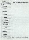
A typical complete ELF file, Figure 14, contains quite a few sections for code, data, relocation information, linker symbols, and debugger symbols. If the file is a C++ program, it will probably also contain .init, .fini, .rel.init, and .rel.fini sections as well.
|
Figure 14: Sample relocatable ELF file
ELF header .text .data .rodata .bss .sym .rel.text .rel.data .rel.rodata .line .debug .strtab (section table, not considered to be a section) |
|
Figure 15: ELF program header
|
An executable usually has only a handful of segments, a read-only one for the code and read-only data, and a read-write one for read/write data. All of the loadable sections are packed into the appropriate segments so the system can map the file with one or two operations.
ELF files extend the ``header in the address space'' trick used in QMAGIC a.out files to make the executable files as compact as possible at the cost of some slop in the address space. A segment can start and end at arbitrary file offsets, but the virtual starting address for the segment must have the same low bits modulo the alignment as the starting offset in the file, i.e, must start in the same offset on a page. The system maps in the entire range from the page where the segment starts to the page where the segment ends, even if the segment logically only occupies part of the first and last pages mapped. Figure 16 shows a typical segment arrangement.
|
Figure 16: ELF loadable segments
|l|n|n|l|. _ File offset Load address Type _ ELF header 0 0x8000000 _ Program header 0x40 0x8000040 _ Read only text 0x100 0x8000100 LOAD, Read/Execute (size 0x4500) _ Read/write data 0x4600 0x8005600 LOAD, Read/Write/Execute (file size 0x2200, memory size 0x3500) _ non-loadable info and optional section headers |
The mapped text segment consists of the ELF header, program header, and read-only text, since the ELF and program headers are in the same page as the beginning of the text. The read/write but the data segment in the file starts immediately after the text segment. The page from the file is mapped both read-only as the last page of the text segment in memory and copy-on-write as the first page of the data segment. In this example, if a computer has 4K pages, and in an executable file the text ends at 0x80045ff, then the data starts at 0x8005600. The file page is mapped into the last page of the text segment at location 0x8004000 where the first 0x600 bytes contain the text from 0x8004000-0x80045ff, and into the data segment at 0x8005000 where the rest of the page contain the initial contents of data from 0x8005600-0x80056ff.
The BSS section again is logically continuous with the end of the read write sections in the data segment, in this case 0x1300 bytes, the difference between the file size and the memory size. The last page of the data segment is mapped in from the file, but as soon as the operating system starts to zero the BSS segment, the copy-on-write system makes a private copy of the page.
If the file contains .init or .fini sections, those sections are part of the read only text segment, and the linker inserts code at the entry point to call the .init section code before it calls the main program, and the .fini section code after the main program returns.
An ELF shared object contains all the baggage of a relocatable and an executable file. It has the program header table at the beginning, followed by the sections in the loadable segments, including dynamic linking information. Following sections comprising the loadable segments are the relocatable symbol table and other information that the linker needs while creating executable programs that refer to the shared object, with the section table at the end.
An object file starts with some ESD records that define the csects and all symbols, then the TXT records, the RLD records and the END. There's quite a lot of flexibility in the order of the records. Several TXT records can redefine the contents of a single location, with the last one in the file winning. This made it possible (and not uncommon) to punch a few ``patch'' cards to stick at the end of an object deck, rather than reassembling or recompiling.
|
Figure 17: IBM object record format
|
|
Figure 18: ESD format
|
Each ESD records defines up to three symbols with sequential ESIDs. Symbols are up to eight EBCDIC characters. The symbol types are:
|
Figure 19: TXT format
|
|
Figure 20: RLD format
|
Each entry has the ESIDs of the target and the pointer, a flag byte, and the csect-relative address of the pointer. The flag byte has bits giving the type of reference (code, data, PR, or CXD), the length (1, 2, 3, or 4 bytes), a sign bit saying whether to add or subtract the relocation, and a "same" bit. If the "same" bit is set, the next entry omits the two ESIDs and uses the same ESIDs as this entry.
|
Figure 21: END format
|
Disk based systems either store object files as card images, or use a variant version of the format with the same record types but much longer records without sequence numbers. The linkers for DOS (IBM's lightweight operating system for the 360) produce a simplified output format with in effect one csect and a stripped down RLD without ESIDs.
Within object files, the individual named csects permit a programmer or linker to arrange the modules in a program as desired, putting all the code csects together, for example. The main places this format shows its age is in the eight-character maximum symbol length, and no type information about individual csects.
Windows developed in an underpowered environment with slow processors, limited RAM, and originally without hardware paging, so there was always an emphasis on shared libraries to save memory, and ad-hoc tricks to improve performance, some of which are apparent in the PE/COFF design. Most Windows executables contain resources, a general term that refers to objects such as cursors, icons, bitmaps, menus, and fonts that are shared between the program and the GUI. A PE file can contain a resource directory for all of the resources the program code in that file uses.
PE executable files are intended for a paged environment, so pages from a PE file are usually be mapped directly into memory and run, much like an ELF executable. PE's can be either EXE programs or DLL shared libraries (known as dynamic link libraries). The format of the two is the same, with a status bit identifying a PE as one or the other. Each can contain a list of exported functions and data that can be used by other PE files loaded into the same address space, and a list of imported functions and data that need to be resolved from other PE's at load time. Each file contains a set of chunks analogous to ELF segments that have variously been called sections, segments, and objects. We call them sections here, the term that Microsoft now uses.
A PE file, Figure 22, starts with a small DOS .EXE file that prints out something like "This program needs Microsoft Windows." (Microsoft's dedication to certain kinds of backward compatibility is impressive.) A previously unused field at the end of the EXE header points to the PE signature, which is followed by the file header which consists of a COFF section and the ``optional'' header, which despite its name appears in all PE files, and a list of section headers. The section headers describe the various sections of the file. A COFF object file starts with the COFF header, and omits the optional header.

|
Figure 22: Microsoft PE and COFF file
DOS header (PE only) DOS program stub (PE only) PE signature (PE only) COFF header Optional header (PE only) Section table Mappable sections (pointed to from section table) COFF line numbers, symbols, debug info (optional in PE File) |
Figure 23 shows the PE, COFF, and "optional" headers. The COFF header describes the contents of the file, with the most important values being the number of entries in the section table, The "optional" header contains pointers to the most commonly used file sections. Addresses are all kept as offsets from the place in memory that the program is loaded, also called Relative Virtual Addresses or RVAs.
|
Figure 23: PE and COFF header
PE signature
COFF header
Optional header that follows PE header, not present in COFF objects
Directories are, in order: |
Each PE file is created in a way that makes it straightforward for the system loader to map it into memory. Each section is physically aligned on a disk block boundary or greater (the filealign value), and logically aligned on a memory page boundary (4096 on the x86.) The linker creates a PE file for a specific target address at which the file will be mapped (imagebase). If a chunk of address space at that address is available, as it almost always is, no load-time fixups are needed. In a few cases such as the old win32s compatbility system target addresses aren't available so the loader has to map the file somewhere else, in which case the file must contain relocation fixups in the .reloc section that tell the loader what to change. Shared DLL libraries also are subject to relocation, since the address at which a DLL is mapped depends on what's already occupying the address space.
Following the PE header is the section table, an array of entries like Figure 24.
|
Figure 24: Section table
|
Each section has both a file address and size (PointerToRawData and SizeOfRawData) and a memory address and size (VirtualAddress and VirtualSize) which aren't necessarily the same. The CPU's page size is often larger than the disk's block size, typically 4K pages and 512 byte disk blocks, and a section that ends in the middle of a page need not have blocks for the rest of the page allocated, saving small amounts of disk space. Each section is marked with the hardware permissions appropriate for the pages, e.g. read+execute for code and read+write for data.
COFF files can also have several other section types not used in PE. The most notable is the .drective section which contains text command strings for the linker. Compilers usually use .drective to tell the linker to search the appropriate language-specific libraries. Some compilers including MSVC also include linker directives to export code and data symbols when creating a DLL. (This mixture of commands and object code goes way back; IBM linkers accepted mixed card decks of commands and object files in the early 1960s.)
All of the formats we've seen so far are intended for environments with random access disks and enough RAM to do compiler and linker processing in straightforward ways. OMF dates from the early days of microprocessor development when memories were tiny and storage was often punched paper tapes. As a result, OMF divides the object file into a series of short records, Figure 25. Each record contains a type byte, a two-byte length, the contents, and a checksum byte that makes the byte-wise sum of the entire record zero. (Paper tape equipment had no built-in error detection, and errors due to dust or sticky parts were not rare.) OMF files are designed so that a linker on a machine without mass storage can do its job with a minimum number of passes over the files. Usually 1 1/2 passes do the trick, a partial pass to find the symbol names which are placed near the front of each file, and then a full pass to do the linking and produce the output.
|
|
Figure 25: OMF record format
picture of -- type byte -- two-byte length -- variable length data -- checksum byte |
OMF is greatly complicated by the need to deal with the 8086 segmented architecture. One of the major goal of an OMF linker is to pack code and data into a minimum number of segments and segment groups. Every piece of code or data in an OMF object is assigned to a segment, and each segment in turn can be assigned to a segment group or segment class. (A group must be small enough to be addressed by a single segment value, a class can be any size, so groups are used for both addressing and storage management, while classes are just for storage management.) Code can reference segments and groups by name, and can also reference code within a segment relative to the base of the segment or the base of the group.
OMF also contains some support for overlay linking, although no OMF linker I know of has ever supported it, taking overlay instructions instead from a separate directive file.
OMF uses several coding techniques to make records as short as possible. All name strings are variable length, stored as a length byte followed by characters. A null name (valid in some contexts) is a single zero byte. Rather than refer to segments, symbols, groups, etc. by name, an OMF module lists each name once in an LNAMES record and subsequently uses a index into the list of names to define the names of segments, groups, and symbols. The first name is 1, the second 2, and so forth through the entire set of names no matter how many LNAMES records they might have taken. (This saves a small amount of space in the not uncommon case that a segment and an external symbol have the same name since the definitions can refer to the same string.) Indexes in the range 0 through 0x7f are stored as one byte. Indexes from 0x80 through 0x7fff are stored as two bytes, with the high bit in the first byte indicating a two-byte sequence. Oddly, the low 7 bits of the first byte are the high 7 bits of the value and the second byte is the low 8 bits of the value, the opposite of the native Intel order. Segments, groups, and external symbols are also referred to by index, with separate index sequences for each. For example, assume a module lists the names DGROUP, CODE, and DATA, defining name indexes 1, 2, and 3. Then the module defines two segments called CODE and DATA, referring to names 2 and 3. Since CODE is the first segment defined, it will be segment index 1 and DATA will be segment index 2.
The original OMF format was defined for the 16 bit Intel architecture. For 32 bit programs, there are new OMF types defined for the record types where the address size matters. All of the 16 bit record types happened to have even numerical codes, so the corresponding 32 bit record types have the odd code one greater than the 16 bit type.
|
Figure 26: Typical OMF record sequence
THEADR program name COMENT flags and options LNAMES list of segment, group, and class names SEGDEF segment (one record per segment) GRPDEF group (one record per group) PUBDEF global symbols EXTDEF undefined external symbols (one per symbol) COMDEF common blocks COMENT end of pass1 info LEDATA chunk of code or data (multiple) LIDATA chunk of repeated data (multiple) FIXUPP relocations and external ref fixups, each following the LEDATA or LIDATA to which it refers MODEND end of module |
The file starts with a THEADR record that marks the start of the module and gives the name of the module's source file as a string. (If this module were part of a library, it would start with a similar LHEADR record.)
The second record is a badly misnamed COMENT record which contains configuration information for the linker. Each COMENT record contains some flag bits saying whether to keep the comment when linked, a type byte, and the comment text. Some comment types are indeed comments, e.g., the compiler version number or a copyright notice, but several of them give essential linker info such as the memory model to use (tiny through large), the name of a library to search after processing this file, definitions of weak external symbols, and a grab-bag of other types of data that vendors shoe-horned into the OMF format.
Next comes a series of LNAMES records that list all of the names used in this module for segments, groups, classes, and overlays. As noted above, the all the names in all LNAMES are logically considered an array with the index of the first name being 1.
After the LNAMES record come SEGDEF records, one for each segment defined in the module. The SEGDEF includes an index for the name of the segment, and the class and overlay if any it belongs to. Also included are the segment's attributes including its alignment requirements and rules for combining it with same-name segments in other modules, and its length.
Next come GRPDEF records, if any, defining the groups in the module. Each GRPDEF has the index for the group name and the indices for the segments in the group.
PUBDEF records define "public" symbols visible to other modules. Each PUBDEF defines one or more symbols within a single group or segment. The record includes the index of the segment or group and for each symbol, the symbol's offset within the segment or group, its name, and a one-byte compiler-specific type field.
EXTDEF records define undefined external symbols. Each record contains the name of one symbol and a byte or two of debugger symbol type. COMDEF records define common blocks, and are similar to EXTDEF records except that they also define a minimum size for the symbol. All of the EXTDEF and COMDEF symbols in the module are logically an array, so fixups can refer to them by index.
Next comes an optional specialized COMENT record that marks the end of pass 1 data. It tells the linker that it can skip the rest of the file in the first pass of the linking process.
The rest of the file consists of the actual code and data of the program, intermixed with fixup records containing relocation and external reference information. There are two kinds of data records LEDATA (enumerated) and LIDATA (iterated). LEDATA simply has the segment index and starting offset, followed by the data to store there. LIDATA also starts with the segment and starting offset, but then has a possibly nested set of repeated blocks of data. LIDATA efficiently handles code generated for statements like this Fortran:
INTEGER A(20,20) /400*42/
A single LIDATA can have a two- or four-byte block containing 42 and repeat it 400 times.
Each LEDATA or LEDATA that needs a fixup must be immediately followed by the FIXUPP records. FIXUPP is by far the most complicated record type. Each fixup requires three items: first the target, the address being referenced, second the frame, the position in a segment or group relative to which the address is calculated, and third the location to be fixed up. Since it's very common to refer to a single frame in many fixups and somewhat common to refer to a single target in many fixups, OMF defines fixup threads, two-bit codes used as shorthands for frames or targets, so at any point there can be up to four frames and four targets with thread numbers defined. Each thread number can be redefined as often as needed. For example, if a module includes a data group, that group is usually used as the frame for nearly every data reference in the module, so defining a thread number for the base address of that group saves a great deal of space. In practice a GRPDEF record is almost invariably followed by a FIXUPP record defining a frame thread for that group.
Each FIXUPP record is a sequence of subrecords, with each subrecord either defining a thread or a fixup. A thread definition subrecord has flag bits saying whether it's defining a frame or target thread. A target thread definition contains the thread number, the kind of reference (segment relative, group relative, external relative), the index of the base segment, group or symbol, and optionally a base offset. A frame thread definition includes the thread number, the kind of reference (all the kinds for target definition plus two common special cases, same segment as the location and same segment as the target.)
Once the threads are defined, a fixup subrecord is relatively simple. It contains the location to fix up, a code specifying the type of fixup (16 bit offset, 16 bit segment, full segment:offset, 8 bit relative, etc.), and the frame and target. The frame and target can either refer to previously defined threads or be specified in place.
After the LEDATA, LIDATA, and FIXUPP records, the end of the module is marked by a MODEND record, which can optionally specify the entry point if the module is the main routine in a program.
A real OMF file would contain more record types for local symbols, line numbers, and other debugger info, and in a Windows environment also info to create the imports and exports sections in a target NE file (the segmented 16 bit predecessor of PE), but the structure of the module doesn't change. The order of records is quite flexible, particularly if there's no end of pass 1 marker. The only hard and fast rules are that THEADER and MODEND must come first and last, FIXUPPs must immediately follow the LEDATA and LIDATA to which they refer, and no intra-module forward references are allowed. In particular, it's permissible to emit records for symbols, segments, and groups as they're defined, so long as they precede other records that refer to them.
Nonetheless, now that even small desktop computers have megabytes of RAM and large disks, the OMF division of the object into many small records has become more trouble than it's worth. The small record type of object module was very common up through the 1970s, but is now obsolescent.
Each object format shows the style of the system for which it was defined. Unix systems have historically kept their internal interfaces simple and well-defined, and the a.out and ELF formats reflect that in their relative simplicity and the lack of special case features. Windows has gone in the other direction, with process management and user interface intertwined.
|
Figure 27: Project object format
LINK nsegs nsyms nrels -- segments -- -- symbols -- -- rels -- -- data -- |
The first line is the ``magic number,'' the word LINK.
The second line contains at least three decimal numbers, the number of segments in the file, the number of symbol table entries, and the number of relocation entries. There may be other information after the three numbers for extended versions of the linker. If there are no symbols or relocations, the respective number is zero.
Next comes the segment definitions. Each segment definition contains the segment name, the address where the segment logically starts, the length of the segment in bytes, and a string of code letters describing the segment. Code letters include R for readable, W for writable, and P for present in the object file. (Other letters may be present as well.) A typical set of segments for an a.out like file would be:
.text 1000 2500 RP
.data 4000 C00 RWP
.bss 5000 1900 RW
Segments are numbered in the order their definitions appear, with the first segment being number 1.
Next comes the symbol table. Each entry is of the form:
name value seg type
The name is the symbol name. The value is the hex value of the symbol. Seg is the segment number relative to which the segment is defined, or 0 for absolute or undefined symbols. The type is a string of letters including D for defined or U for undefined. Symbols are also numbered in the order they're listed, starting at 1.
Next come the relocations, one to a line:
loc seg ref type ...
Loc is the location to be relocated, seg is the segment within which the location is found, ref is the segment or symbol number to be relocated there, and type is an architecture-dependent relocation type. Common types are A4 for a four-byte absolute address, or R4 for a four-byte relative address. Some relocation types may have extra fields after the type.
Following the relocations comes the object data. The data for each segment is a single long hex string followed by a newline. (This makes it easy to read and write section data in perl.) Each pair of hex digits represents one byte. The segment data strings are in the same order as the segment table, and there must be segment data for each ``present'' segment. The length of the hex string is determined by the the defined length of the segment; if the segment is 100 bytes long, the line of segment data is 200 characters, not counting the newline at the end.
Project 3-1: Write a perl program that reads an object files in this format and stores the contents in a suitable form in perl tables and arrays, then writes the file back out. The output file need not be identical to the input, although it should be semantically equivalent. For example, the symbols need not be written in the same order they were read, although if they're reordered, the relocation entries must be adjusted to reflect the new order of the symbol table.